
Top of Teensy Cape:

Bottom of Teensy Cape (Includes Jumper Positions):

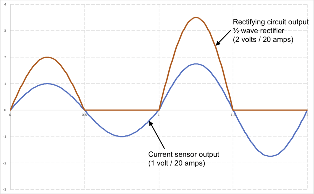
Rectifying Circuits:
- J2 terminal position 23 – Teensy pin 23 (analog 9)
- J2 terminal position 22 – Teensy pin 22 (analog 8)
- J2 terminal position 21 – Teensy pin 21 (analog 7)
The rectifying circuit converts a 60-hertz sine wave shown in Figure 3 to a rectified wave shown in Figure 4. The rectified wave is always positive or zero voltage so analog-to-digital (ADC) converters can digitize the signal.
- Teensy Pin 0 UART1 RX1 is connected to BBB P9_24 UART1 TX1.
- Teensy Pin 1 UART1 TX1 is connected to BBB P9_26 UART1 RX1.
In order for the BBB to accomplish serial communication over UART, pins P9_24 and P2_26 must be configured. Instructions for doing so can be found here.
Cape Connection Mappings:
Terminal J1 Connections to the Teensy:
| J1 Terminal Position | Connection Type | Teensy Pin | Teensy Pin Default Function | Teensy Pin Serial Function |
|---|---|---|---|---|
| GND | Direct | GND | GND | – |
| 0 | Direct to Teensy and BBB | 0 | DIO 0 | UART1 RX1 |
| 1 | Direct to Teensy and BBB | 1 | DIO 1 | UART1 TX1 |
| 2 | R14 Jumper | 2 | DIO 2 | – |
| 3 | R17 Jumper | 3 | DIO 3 | – |
| 4 | R18 Jumper | 4 | DIO 4 | – |
| 5 | R19 Jumper | 5 | DIO 5 | – |
| 6 | R20 Jumper | 6 | DIO 6 | – |
| 7 | R21 Jumper | 7 | DIO 7 | UART RX3 |
| 8 | R22 Jumper | 8 | DIO 8 | UART TX3 |
| 9 | R23 Jumper | 9 | DIO 9 | UART RX2 |
| 10 | R24 Jumper | 10 | DIO 10 | UART TX2 |
| 11 | R25 Jumper | 11 | DIO 11 | – |
| 12 | R26 Jumper | 12 | DIO 12 | – |
Terminal J2 Connections to the Teensy:
| J2 Terminal Position | Connection Type | Teensy Pin | Teensy Pin Default Function |
|---|---|---|---|
| Vin | Direct | Vin | Vin |
| AGN | Direct | AGN | AGN |
| 3.3V | Direct | 3.3V | 3.3V |
| 23 | Direct via rectify circuit | 23 | Analog 9 |
| 22 | Direct via rectify circuit | 22 | Analog 8 |
| 21 | Direct via rectify circuit | 21 | Analog 7 |
| 20 | R51 Jumper | 20 | Analog 6 |
| 19 | R50 Jumper | 19 | Analog 5 |
| 18 | R49 Jumper | 18 | Analog 4 |
| 17 | R48 Jumper | 17 | Analog 3 |
| 16 | R47 Jumper | 16 | Analog 2 |
| 15 | R46 Jumper | 15 | Analog 1 |
| 14 | R45 Jumper | 14 | Analog 0 |
| 13 | None | None | None |
Terminal J1 Connections to the BeagleBone Black:
| J1 Terminal Position | Connection Type | BBB Pin | BBB Pin Default Function | BBB Pin Serial Function |
|---|---|---|---|---|
| GND | Direct | GND | P8_1, P8_2, P9_1, P9_2, P9_43, P9_44, P9_45, P9_46 | – |
| 0 | Direct to Teensy and BBB | P9_24 | GPIO_15 | UART1 TX1 |
| 1 | Direct to Teensy and BBB | P9_26 | GPIO_14 | UART1 RX1 |
| 2 | R37 Jumper | P9_11 | GPIO_30 | UART4 RX4 |
| 3 | R36 Jumper | P9_12 | GPIO_60 | – |
| 4 | R35 Jumper | P9_13 | GPIO_31 | UART4 TX4 |
| 5 | R34 Jumper | P9_14 | GPIO_50 | – |
| 6 | R33 Jumper | P9_15 | GPIO_48 | – |
| 7 | R32 Jumper | P9_16 | GPIO_51 | – |
| 8 | R31 Jumper | P9_17 | GPIO_5 | – |
| 9 | R30 Jumper | P9_18 | GPIO_4 | – |
| 10 | R29 Jumper | P9_19 | I2C2_SCL | – |
| 11 | R28 Jumper | P9_20 | I2C2_SDA | – |
| 12 | R27 Jumper | P9_21 | GPIO_3 | – |
Terminal J2 Connections to the BeagleBone Black:
| J2 Terminal Position | Connection Type | BBB Pin | BBB Pin Default Function |
|---|---|---|---|
| Vin | Direct | P9_5,P9_6 | Vcc |
| AGN | None | None | None |
| 3.3V | None | None | None |
| 23 | None | None | None |
| 22 | None | None | None |
| 21 | None | None | None |
| 20 | R44 Jumper | P9_35 | AIN6 |
| 19 | R43 Jumper | P9_36 | AIN5 |
| 18 | R42 Jumper | P9_33 | AIN4 |
| 17 | R41 Jumper | P9_38 | AIN3 |
| 16 | R40 Jumper | P9_37 | AIN2 |
| 15 | R39 Jumper | P9_40 | AIN1 |
| 14 | R38 Jumper | P9_39 | AIN0 |
| 13 | None | None | None |
Current Measurement Error
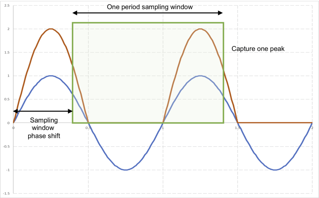
One period sampling window
The Teensy code should be written such that it samples the current for a time equal to the period of a single 60 hertz cycle (~0.016667 secs). This will guarantee that one (and only one) current peak will be measured since we don’t know the phase shift of the sampling window.
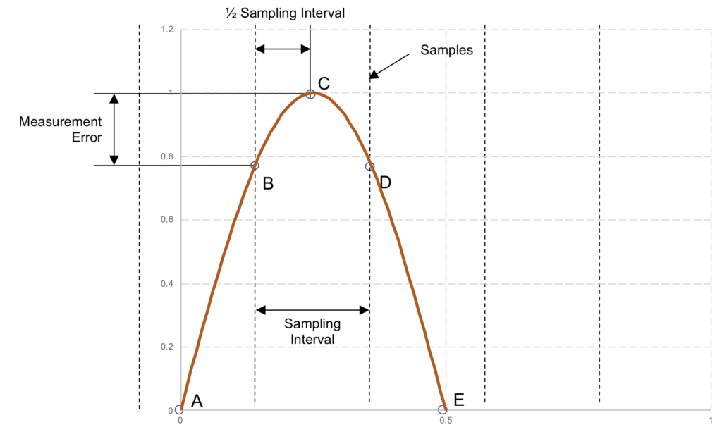
Max error occurs when sample straddles peak
The maximum measurement error occurs when the samples are taken 1/2 of the sampling interval from the peak of the current. Since the sampling window phase shift is not known, assuming the samples straddle the peak of the current provides the most conservative (worst case) current measurement error.
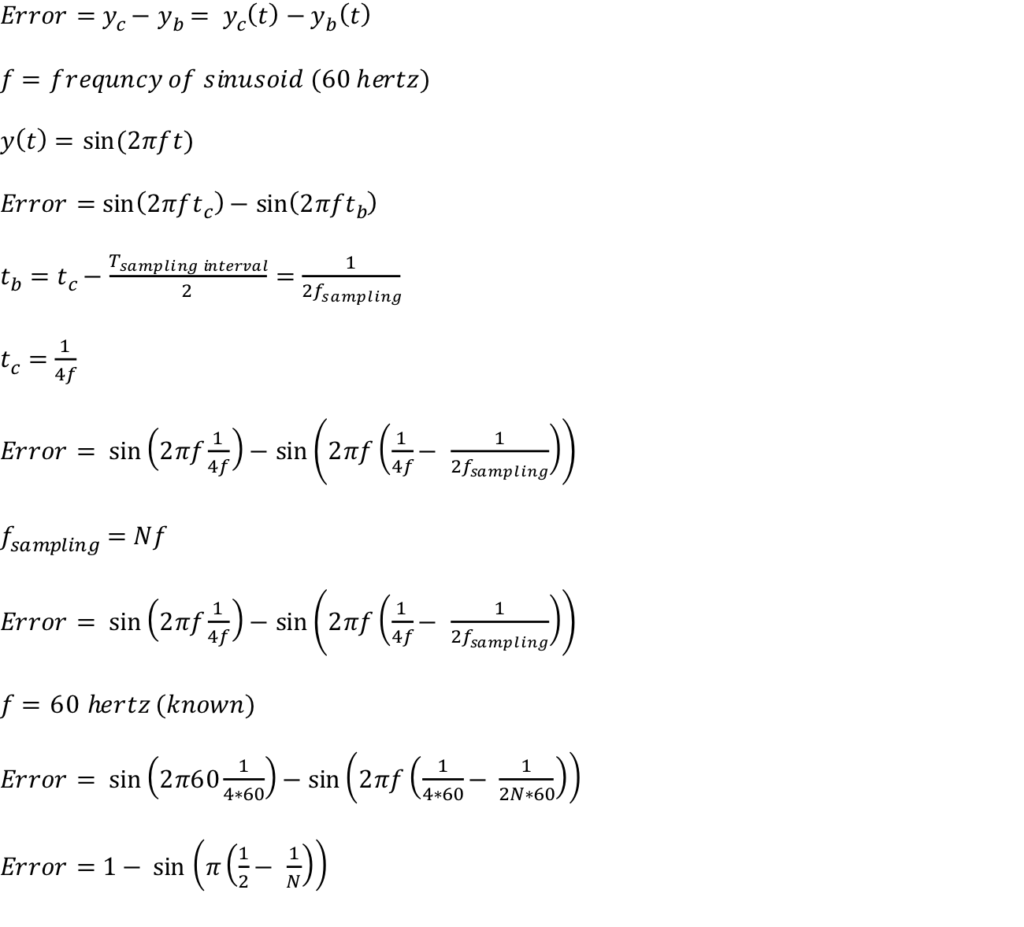
Error calculations
The maximum measurement error due to digitization can be calculated for a given sampling frequency as follows:
Example Error Values
| Sampling Frequency (hertz) | N | Error % |
| 300 | 5 | 19.10% |
| 400 | 6.67 | 10.90% |
| 1000 | 16.67 | 1.77% |
| 3000 | 50 | 0.20% |
| 6000 | 100 | 0.05% |
| 10000 | 166.67 | 0.02% |
| 12000 | 200 | 0.01% |